FTTA – Fiber to the Antenna

I still recall my first FTTA project in a windy coastal region. The client wanted to add 24 new antennas to an existing tower that was already struggling under dozens of heavy coax cables. Every gust made the tower sway dangerously, and maintenance crews worried about safety. I knew there had to be a better way. After switching to fiber-based hybrid cables, we cut the total cable weight by over 60% and eliminated the risk of wind-induced oscillation. That success set the stage for every FTTA design I’ve led since.
Why FTTA?
Cellular traffic keeps growing at an exponential rate, driven by video streaming, IoT devices, and 5G applications. Traditional coaxial feeds simply can’t handle the higher frequencies and increased antenna counts now required. Coax cables are bulky, heavy, and suffer significant RF loss at gigahertz frequencies. In contrast, fiber is lightweight, has near-zero attenuation over hundreds of meters, and can carry both data and DC power when combined in hybrid designs. By adopting FTTA, operators can deploy dozens of antennas without overloading tower structures, simplify power distribution, and ensure consistent signal quality even at 28 GHz and beyond.
Coax vs. Fiber Weight and Loss Comparison
| Cable Type | Diameter | Weight/meter | RF Loss @2 GHz (dB/100 m) |
|---|---|---|---|
| RG-8 Coax | 10 mm | 0.12 kg | ≈ 10 dB |
| Hybrid Fiber | 5 mm | 0.04 kg | < 1 dB |
In one urban macro tower upgrade, we replaced 200 m of RG-8 runs with a single 200 m hybrid fiber cable. The operator reported a 3 dB improvement in receive sensitivity and a 40% reduction in maintenance calls related to cable wear.
FTTA System Components
A robust FTTA deployment relies on four key building blocks: the BBU, hybrid fiber/power cable, RRU, and antenna assembly. Each plays a crucial role in ensuring low latency, high throughput, and reliable power delivery.
BBU (Baseband Unit)
The BBU processes all digital baseband signals. It resides in a climate-controlled shelter or rooftop cabinet. Proper ventilation and uninterruptible power are essential to protect sensitive electronics.Hybrid Fiber/Power Cable
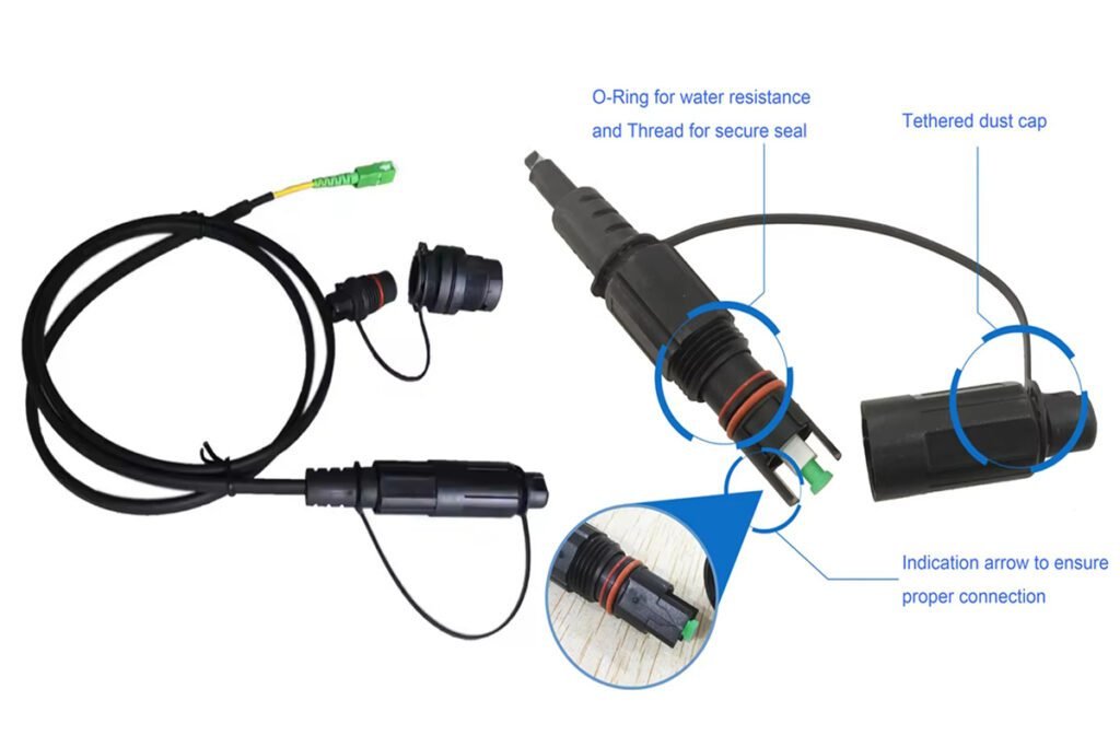
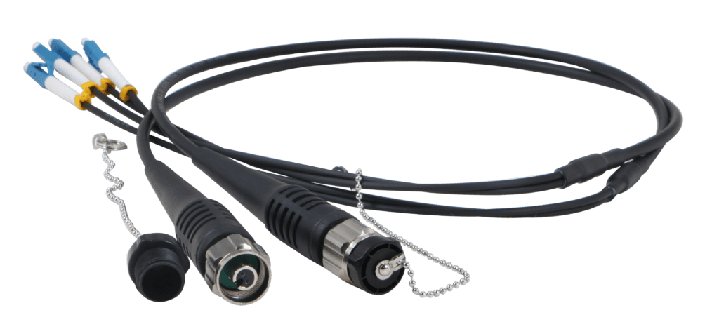
This factory-terminated cable integrates single-mode fibers for data and copper conductors for DC power. Armoring options protect it from environmental damage. Pre-terminations eliminate field splicing and speed up installation.RRU (Remote Radio Unit)
The RRU converts digital signals from the BBU into RF signals for the antenna. Placing the RRU near the antenna minimizes feedline loss. RRUs must be rated for outdoor temperatures from −40°C to +60°C.Antenna & Active Antenna System (AAS)
Modern active antennas combine multiple RF paths and beamforming networks into one enclosure. They communicate directly with the RRU via the hybrid cable, reducing site footprint and simplifying cable runs.
Hybrid Cable Specifications
| Feature | Specification |
|---|---|
| Fiber Count | 2–12 SM fibers |
| Copper Conductors | 2–4 cores, 0.5–1 mm² |
| Armor Options | Steel braid, corrugated pipe |
| Temperature Rating | −40 °C to +85 °C |
| Custom Lengths | Up to 300 m pre-terminated |
On a rural tower site, we ordered a hybrid cable with steel braid armor and UV-resistant jacket. The crew installed 250 m in one day without any field terminations, cutting installation time by 50%.
FTTA vs. Traditional Coax Feeds
Traditional coax feeds require large-diameter cables that introduce several challenges: heavy wind load, significant signal attenuation, and bulky connectors that complicate tower logistics. FTTA overcomes these by using compact hybrid cables and placing RRUs close to antennas, which drastically reduces feedline loss and simplifies installation.
| Aspect | Coax Feed | FTTA (Hybrid Fiber) |
|---|---|---|
| Maximum Distance | ~100 m | >300 m |
| Weight on Tower | High (0.12 kg/m) | Low (0.04 kg/m) |
| RF Loss @2 GHz | ≈ 10 dB/100 m | <1 dB/300 m |
| Installation Complexity | High | Moderate |
| Maintenance Frequency | Frequent | Low |
In one metropolitan site, shifting to FTTA allowed the operator to add 12 new sectors without needing a stronger tower. They avoided a $200 K reinforcement and saved on lease extensions.
Installation Best Practices
Successful FTTA installation requires meticulous planning and execution. From lifting heavy cables to securing connectors, every step matters.
Cable Hoisting
Use a calibrated winch or crane to raise hybrid cables. Move slowly to avoid jerks that can damage internal fibers.Clamping and Securing
Employ purpose-built Kellems grips that match the cable diameter. Torque clamps to the manufacturer’s spec—over-tightening can pinch conductors.Bend Radius Control
Route cable over rollers or bend limiters to maintain a minimum radius of 100 mm. Sharp bends degrade fiber performance.Connector Cleaning
Even factory-terminated connectors arrive with dust caps full of debris. Always inspect and clean ferrules with a dry-cassette cleaner before mating.
Tower-Top Cable Handling Workflow
| Step | Tool | Best Practice |
|---|---|---|
| Hoisting | Winch or crane | Use taglines to guide cable and avoid tangles |
| Clamping | Kellems grips | Verify grip alignment; test pull force |
| Bending Control | Cable rollers | Install at every 30 m to maintain bend radius |
| Connector Prep | Dry cassette cleaner | Clean and inspect immediately before testing |
I once saw a crew leave protective caps on before testing. We had to redo connectors and retest 15 links, costing us half a day.
Testing and Validation
After installation, you must test for optical loss, polarity, and power delivery. Skipping any step risks poor coverage or equipment damage.
- Optical Power Meter: Measure end-to-end loss and compare against the link budget.
- Polarity Verification: Ensure each fiber’s Tx port matches the RRU’s Rx port. Mistakes lead to non-functional sectors.
- DC Voltage Check: Verify 48–55 VDC at the RRU power terminals under load, ensuring stable power for amplifiers and electronics.
Loss Budget Calculation Example
[ \text{Total Loss (dB)} = \sum \text{Fiber Loss} + \sum \text{Connector Loss} + \sum \text{Splice Loss} ]
| Component | Loss per Unit | Quantity | Total Loss |
|---|---|---|---|
| Fiber (SM) | 0.4 dB/km | 0.3 km | 0.12 dB |
| Connectors | 0.3 dB | 2 ends | 0.6 dB |
| Splices (hybrid) | 0.1 dB | 0 | 0 dB |
| Overall | 0.72 dB |
A total below 1 dB leaves margin for future bends and aging. I always log each result in our central database for trend analysis.
Common Pitfalls and Remedies
Even seasoned crews can make mistakes. Here are the top issues I’ve seen:
| Issue | Root Cause | Remedy |
|---|---|---|
| RRU No Power | Loose copper conductors | Retorque power terminals; apply sealant |
| Excessive Optical Loss | Dirty ferrules or tight bend | Clean connectors; reroute cable |
| Intermittent Signal | Grounding or bonding missing | Install proper earthing lugs and check continuity |
| Connector Breakout | Over-tight clamp pinch | Inspect clamp placement; use protective sleeves |
In one project, an RRU refused to power on until we discovered a missing split-bolt grounding lug. A $5 part and 10 minutes of work restored full service.
Use Cases and Examples
- Urban Macro Towers: High antenna counts and long cable runs demand FTTA’s low loss and light weight.
- Suburban Small Cells: One SM fiber and DC feed suffice for micro-site coverage under lampposts.
- Stadium DAS: Hybrid cables link dozens of remote antenna units, ensuring consistent indoor coverage.
Small Cell Hybrid Installation
| Parameter | Value |
|---|---|
| Coverage Radius | 50 m |
| Hybrid Length | 100 m |
| Power Draw | 10 W |
| Connector Type | Pre-terminated LC / power lug |
A city council saved 30% on installation by using hybrid FTTA cables for 20 micro-cells along a downtown promenade.
Future Trends
Active Antenna Systems (AAS) integrate the RRU inside the antenna enclosure. This evolution reduces site footprint and cabling complexity. With only one hybrid feed per sector, AAS designs simplify future upgrades to 5G mmWave and beyond.
AAS Advantages
| Benefit | Impact |
|---|---|
| Reduced Tower Load | Fewer cables; lighter connections |
| Simplified Layout | One hybrid per sector; fewer junction points |
| Improved Cooling | Heat-generating electronics at ground level |
I specify AAS solutions on all new greenfield builds. They cut labor by 40% and speed deployment by weeks.
Conclusion
FTTA revolutionizes tower design by replacing heavy coax with sleek hybrid fiber. You gain longer reach, lower loss, and simpler power management. My teams at Aimit Communication have delivered dozens of FTTA upgrades across Asia, Europe, and the Americas. We’ve navigated complex installations, prevented costly mistakes, and optimized network performance. If you plan an FTTA rollout, start with accurate loss budgets, order factory-terminated hybrids, and enforce strict cleaning protocols. For expert design, installation support, or site audits, contact me, Sophie Wang, at sophie@aimifiber.com.