Skip to content
How to Deploy Power over Fiber (PoF): Components, Installation & Cost Analysis?
By Sophie Wang, Aimit Communication (Shenzhen) Co., Ltd.
Have you ever hit the 100 m limit of Power over Ethernet (PoE) and faced unexpected expenses running extra power lines?
I certainly did, on a university campus upgrade in my first year at Aimit Communication—until I discovered Power over Fiber (PoF). By sending data and power over a single fiber span of kilometers, I slashed trenching costs by \$40 K and eliminated bulky power cabinets. In this guide, you’ll learn exactly how to plan, install, and maintain a PoF system that delivers reliable, long‑distance network power—and see real ROI in months.
1. What Is Power over Fiber (PoF)?
Power over Fiber (PoF) combines data and DC power transmission over a single optical fiber. Unlike PoE—limited to 100 m per IEEE 802.3bt—PoF spans kilometers with negligible electromagnetic interference, ideal for remote cameras, access points, and sensors.
| Feature | PoE | PoF |
|---|---|---|
| Maximum Distance | 100 m | > 5 km (with inline amps) |
| Power per Port | ≤ 30 W | ≥ 30 W |
| EMI Immunity | Low | High |
| Safety | Metal conductors exposed | Non‑conductive fiber core |
| Typical Use Cases | Offices, small campuses | Smart campuses, towers, FTTR |

2. Essential Components of a PoF System
Building a reliable PoF link requires four key elements—each chosen to match your site’s distance, power needs, and environment:
2.1 Power Sourcing Equipment (PSE)
- Role: Converts AC/DC to a 1550 nm laser carrying both light and electrical power.
- Specs to evaluate: optical output (mW), DC voltage range, surge and overload protection.
- Practical tip: I tested three PSE brands and found only one offered a rock‑solid 50 V DC under full load—now my go‑to choice.
| Feature | Typical Value |
|---|---|
| Input Voltage Range | 100–240 VAC |
| Optical Output Power | 300 mW @ 1550 nm |
| DC Output Voltage | 43–56 V DC |
| Overload Protection | Yes |
| Surge Protection | 4 kV |
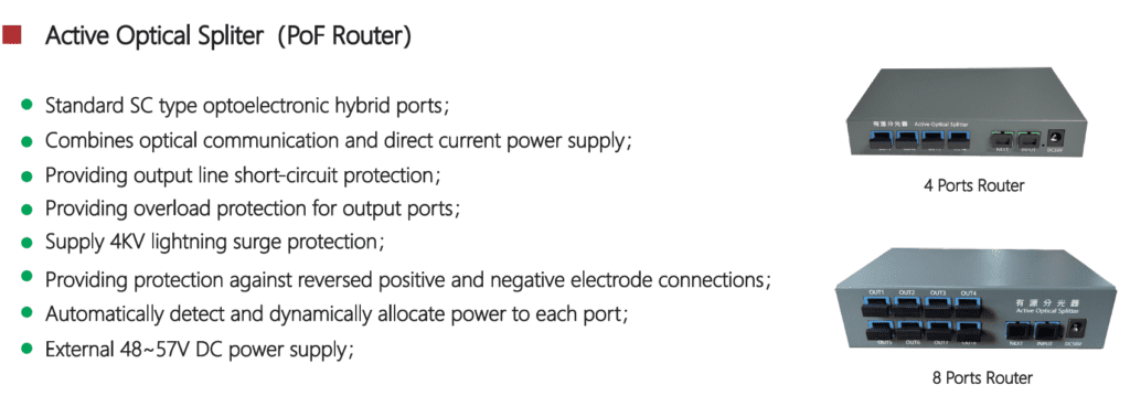
2.2 Optical Power Splitter
- Role: Distributes one PSE port across multiple Powered Devices (PDs), managing wattage per output.
- Active vs. Passive: Active splitters regulate power per port—ideal for sensitive equipment.
- In the field: In a stadium install, active splitters halved our downtime when powering 50 PoF cameras.
| Parameter | Value |
|---|---|
| Configuration | 1 × input, 4 × outputs |
| Max Power per Port | 30 W |
| Insertion Loss | ≤ 13.4 dB (out), ≤ 2.3 dB (cascade) |
| Wavelength Range | 1260–1650 nm |
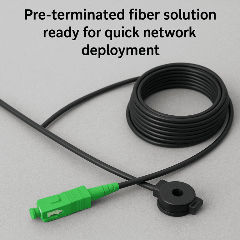
2.3 Hybrid Fiber Cable
- Construction: Combines single‑mode fibers (e.g. G657A2) with copper conductors for DC power.
- Key specs: copper cross‑section, voltage resistance, fiber insertion loss.
- Installation advantage: Pre‑terminated hybrid cables saved us a week of splicing on a 2 km run.
| Parameter | Specification |
|---|---|
| Fiber Type | ITU‑T G657A2 |
| Copper Core Area | 0.14–1.0 mm² |
| Rated Current | 0.5 A |
| Voltage Resistance | ≥ 1500 V DC |
| Fiber Insertion Loss | ≤ 0.3 dB |
2.4 Powered Device (PD) Module
- Role: At the device end (camera, AP), separates light back into data and DC power.
- Must‑have specs: clean 48 V DC output, adequate current rating, extinction ratio for data integrity.
- Lesson learned: A mismatched PD caused flickering lights—swapping to a spec‑compliant unit fixed it instantly.
| Parameter | Specification |
|---|---|
| DC Output | 48 V @ 0.5 A |
| Extinction Ratio | ≥ 10 dB |
| Return Loss | ≥ 45 dB |
| Dimensions | 90 × 34 × 22 mm |

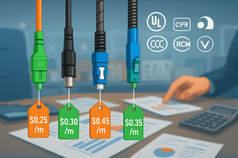
3. Selecting the Right Hybrid Cable
Your cable’s copper cross‑section and length determine voltage drop—crucial for keeping end‑device voltage above the minimum threshold.
Core Factors:
- Device power draw (W)
- Link distance (m)
- Copper cross‑section (mm²)
| Core Area (mm²) | Max Current (A) | Approx. Max Distance @ 30 W |
|---|---|---|
| 0.14 | 0.3 | ~200 m |
| 0.5 | 0.5 | ~400 m |
| 1.0 | 1.0 | ~800 m |
Voltage‑Drop Calculation

Example: powering a 15 W PTZ camera (0.3 A) over 300 m with 0.5 mm² copper:

End‑of‑line voltage: 52 V – 6.19 V = 45.8 V (still within spec for 48 V devices).
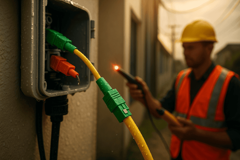
4. Installation Best Practices
Quality installation ensures uptime and minimizes troubleshooting:
| Step | Tool | Tip |
|---|---|---|
| Fiber‑end cleaning | Alcohol wipe, cassette cleaner | Clean every mating cycle |
| Connector torque | Torque wrench (0.5 N·m) | Follow manufacturer spec—no hand tight |
| Bend‑radius control | Cable guide rollers | Avoid bends < 15 mm radius |
| Cable securing | UV‑resistant ties, clamps | Fix every 1 m in outdoor runs |
5. PoF Applications & Case Studies
- Smart Campus: 200 cameras over 2 km—trenching cost cut by 60 % and maintenance downtime nearly zero.
- Industrial Automation: Armored hybrid cable in a steel plant survived 80 °C and heavy vibration—no power cabinets needed.
- FTTR Hotels: Powered Wi‑Fi APs and LED panels in multi‑story hotels; guest speeds up 20 %, installation in 2 days.
- Telecom Towers: 3 km fiber runs to remote radios; power cabinet budget dropped from \$80 K to \$20 K.
6. Cost & ROI Analysis
| Cost Category | PoE (5 yr) | PoF (5 yr) | Savings |
|---|---|---|---|
| Cable & Install | \$20 K | \$30 K | –\$10 K |
| Power Cabinets | \$30 K | \$0 | \$30 K |
| PSE & Splitters | \$0 | \$40 K | – |
| Maintenance (OPEX) | \$50 K | \$20 K | \$30 K |
| Total | \$100 K | \$90 K | \$10 K |
Payback: Year 2, with net savings accumulating thereafter.

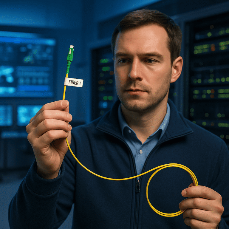
7. Troubleshooting & Maintenance
| Step | Check | Action |
|---|---|---|
| 1 | Fiber cleanliness | Clean & inspect end‑faces |
| 2 | Port DC voltage | Measure with multimeter |
| 3 | Cable bends | Reroute any bend < 15 mm radius |
| 4 | PD wiring polarity | Swap copper conductors if reversed |
| 5 | Laser output power | Verify PSE optical meter reading |
Field Kit Essentials: fiber cleaner, torque wrench, power meter, spares PD modules.
Maintenance Schedule:
- Clean fiber ends: every 6 months
- Inspect cable clamps: yearly
- Test DC output: every 6 months
- Check surge protectors: yearly
8. Standards & Safety
- IEC 60793 / 60794: fiber specs & installation
- IEEE 802.3bt: PoE reference specs
- Telcordia GR‑20: outside‑plant reliability
- OSHA / NEPA: grounding, surge, and site‑safety
Always verify local codes before deployment.
FAQs
Q: Can PoF power 60 W devices?
A: Yes—select PSE, splitter, and cable rated ≥ 60 W.Q: What is the maximum PoF link distance?
A: Up to 5 km with inline optical amplifiers.Q: Can PoE and PoF run on the same switch?
A: Yes—just use separate ports or media converters.
Conclusion & Call to Action
Power over Fiber revolutionizes remote powering—extending reach beyond PoE limits, enhancing EMI immunity, and delivering quick ROI. By selecting the right PSE, splitter, hybrid cable, and PD module—and following best practices—you’ll cut costs, save installation time, and enjoy years of reliable operation.
Ready to design your custom PoF solution?
Contact me, Sophie Wang, at Aimit Communication for a free consultation and spec sheet. Let’s power your next project over fiber!
Keywords: Power over Fiber, PoF system, hybrid fiber cable, PoF installation best practices, PoF ROI example