
Description
The Aimit Hybrid Fiber-Copper Composite Cable is an integrated solution designed for FTTA (Fiber to the Antenna) and remote power applications. By combining optical fibers for data and copper conductors for power in a single robust jacket, it reduces installation time and cabling costs for 5G Base Stations, RRUs (Remote Radio Units), and Security Cameras.
Need a custom spec for your 5G tower project?
We support OEM drum lengths and color codes. [Contact Our Engineers]
Designed for North American Standards:
Available with 12 AWG, 14 AWG, 16 AWG copper conductors to meet NEC standards for remote power distribution.
Key Technical Advantages
- One Cable, Two Functions: Simultaneous transmission of high-bandwidth data and low-voltage power (DC 48V/60V).
- Structure Options:
- Standard: Stranded structure for flexibility.
- Armored: With Steel Tape (PSP) or Steel Wire (SWA) for direct burial and rodent protection.
- Copper Conductors: High-purity Oxygen-Free Copper (OFC) ensures low resistance and stable power delivery over long distances.
- Jacket Material: UV-resistant PE (Outdoor) or LSZH (Indoor/Riser).
Applications (FTTA & DAS)
This hybrid cable is specifically engineered for:
- 5G/4G Mobile Towers: Connecting BBU (Base Band Unit) to RRU (Remote Radio Unit).
- Smart City Infrastructure: Powering remote Wi-Fi APs and CCTV cameras without local power sources.
- DAS (Distributed Antenna Systems): In-building signal coverage.
Specifications (Customizable)
| Parameter | Specification Options |
| Copper Gauge (Power) | 2x1.5mm² (16 AWG), 2x2.5mm² (14 AWG), 2x4.0mm² (12 AWG), 2x6.0mm² (10 AWG) |
| Fiber Count (Data) | 2, 4, 6, 12, 24 Cores (G.652D / G.657A1) |
| Rated Voltage | 300V / 600V (Customizable) |
| Operating Temp | -40°C to +85°C |
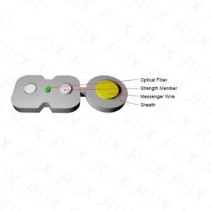
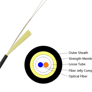
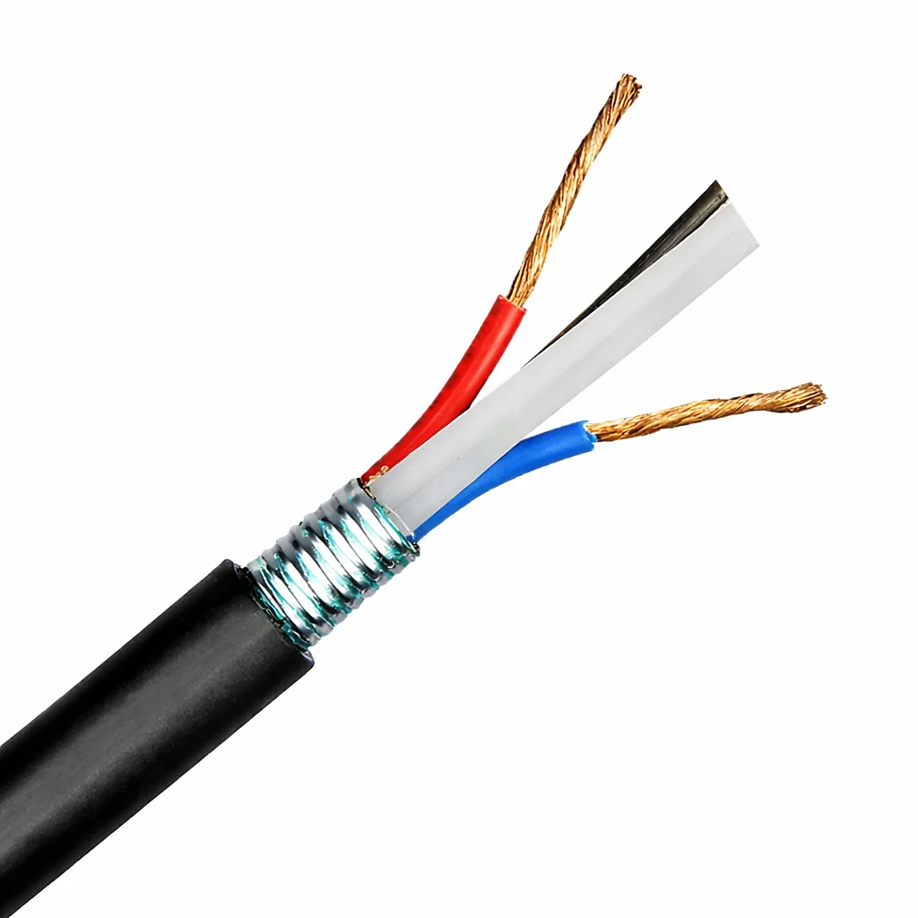
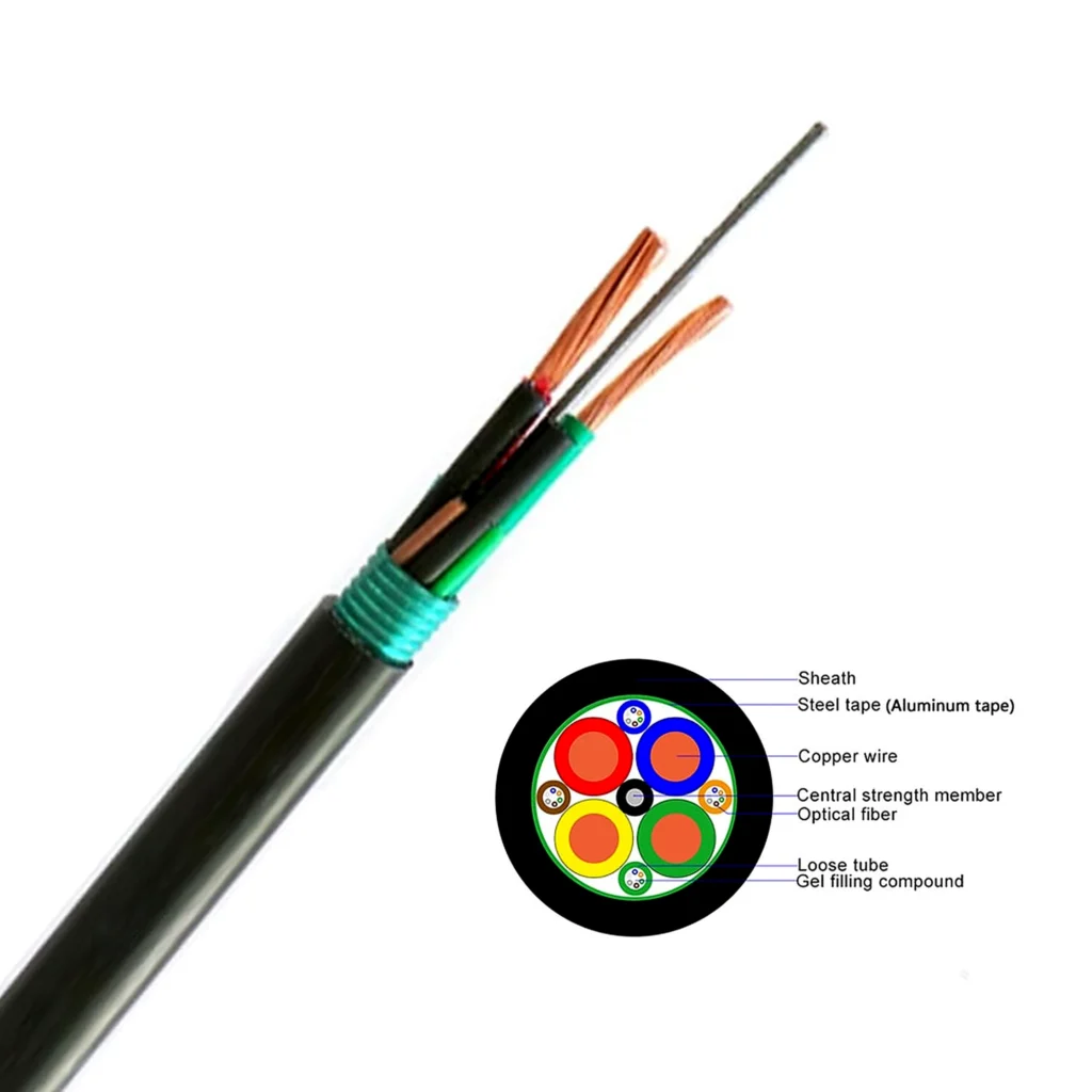
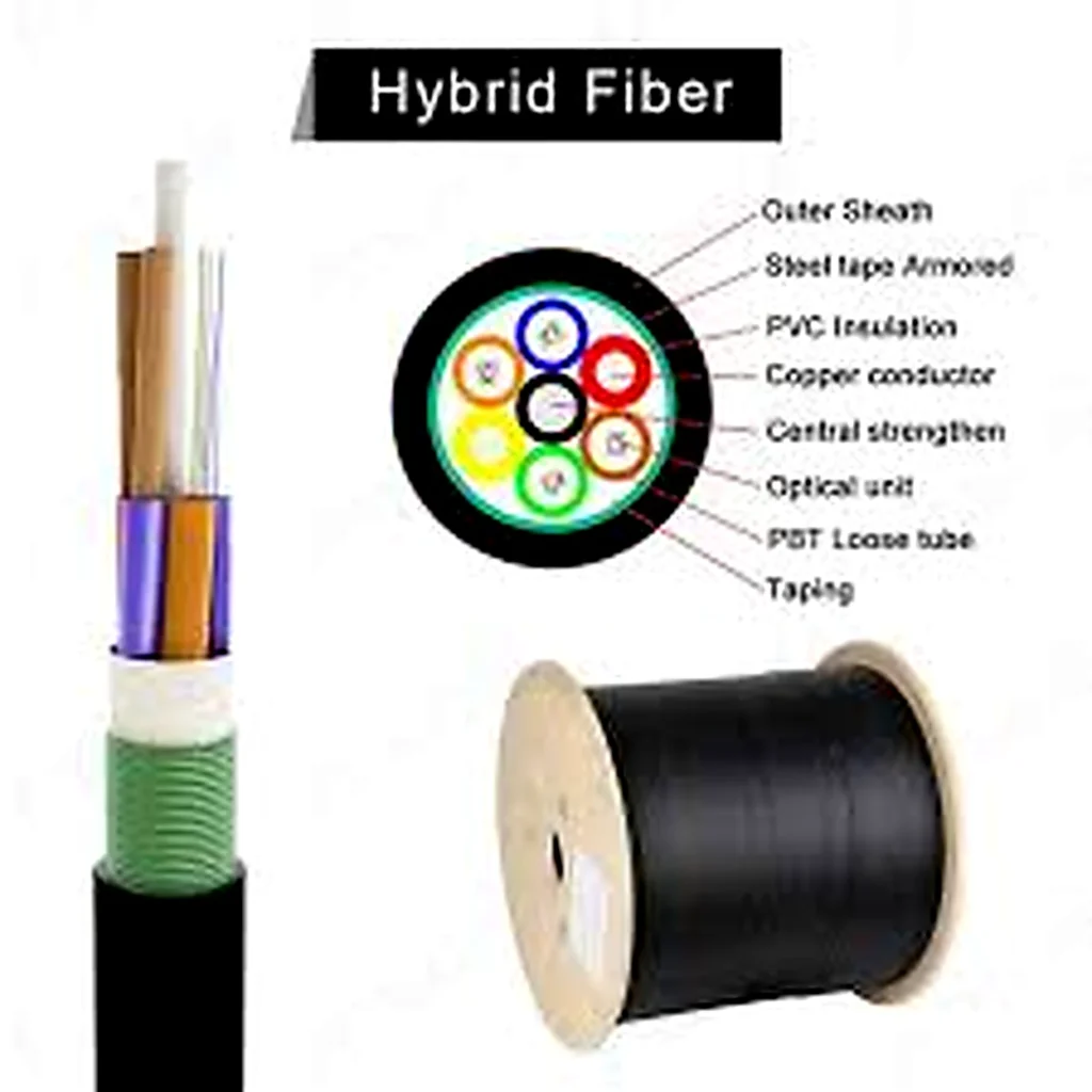
A single hybrid trunk that combines optical transmission and DC power distribution for last-mile active equipment. Typical builds include a tight-buffer fiber sub-cable (e.g., 2F G.657A2) plus copper power conductors within a UV-resistant black sheath; shielding (Al/PET foil) and a tinned-copper drain wire are available to simplify grounding. Cross-sections and parameters are shown in the reference drawings and datasheets.
Where it’s used
- 5G/4G FTTA to Remote Radio Heads (RRH), small cells, rooftop BTS
- DAS and repeater systems in stadiums, tunnels, and venues
- Pole-mounted and perimeter CCTV/PTZ cameras, wireless bridges, IoT gateways
- Long outdoor runs to shelters and cabinets (duct, tray, or aerial with hardware)
Why it helps
- 2-in-1 cable plant: one pull and one BOM cut power + fiber deployment time dramatically.
- Long-reach power: choose copper gauge to match run length and load; typical rated voltage 400/600 V on 12 AWG assemblies.
- Bend-tolerant fiber: G.657A2 sub-cables maintain low loss even in tight routing.
- Outdoor-ready: UV-resistant PE outer sheath; shield + drain wire options for robust EMI control.
Specifications
A) Construction & Materials (typical builds)
| Element | Option / Value | Notes |
|---|---|---|
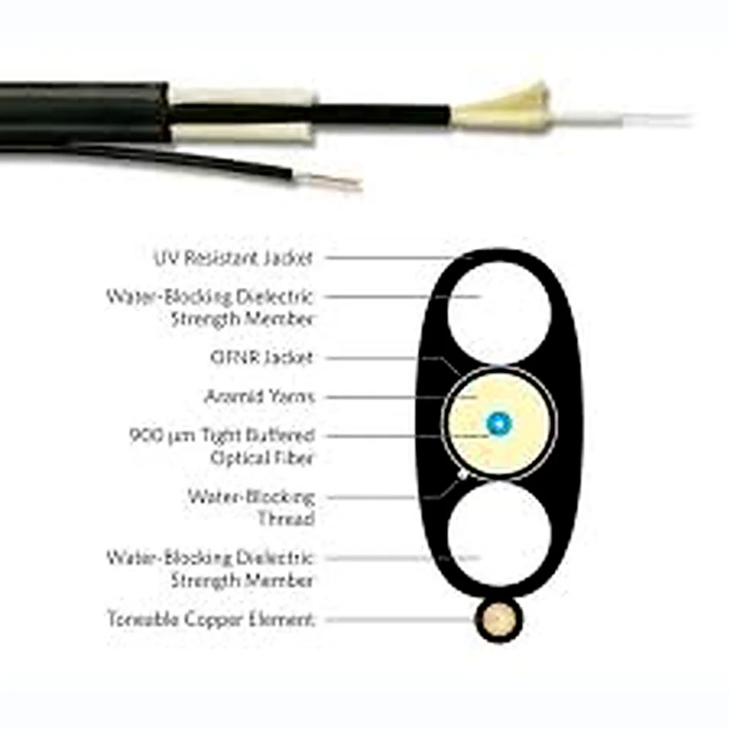
| Optical sub-cable | 1× (2F, G.657A2 tight buffer) | Clean strip for connectorization; |
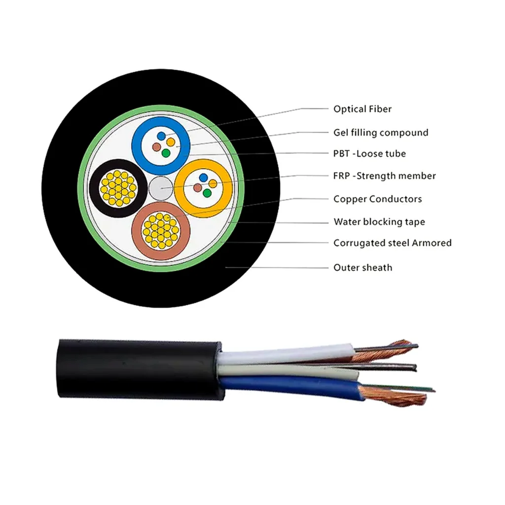
| Power conductors | 3×16 AWG (red/black/green) or 2×14 AWG (red/black) | Stranded bare copper; choose gauge by voltage drop/ampacity. |
| Shielding | Al/PET foil + tinned-copper drain wire | For grounding/EMI control. |
| Strength members | Aramid yarn in optical unit; spiral steel armor optional on sub-cables | For pull/crush resistance. |
| Outer jacket | UV-resistant PE (black); LSZH on request | Outdoor grade; LSZH for indoor transitions. |
| Overall OD | ~9.0 ± 0.2 mm (3×16 AWG build) | Reference dimensional spec. |
| Cable weight | ~107–110 kg/km (typical) | Per 9 mm builds. |
B) Optical Characteristics (typical)
| Fiber type | Attenuation (1310/1550 nm) | Return loss (LC/UPC) | Notes |
|---|---|---|---|
| OS2 G.657A2 | ≤0.4/≤0.3 dB/km (cable) | ≥50 dB | Macro-bend limits verified; insertion loss targets ≤0.30 dB ref plug. |
C) Electrical (representative)
| Conductor | Gauge | Conductor material | Jacket | Rated voltage | Withstand |
|---|---|---|---|---|---|
| Power pair | 2×14 AWG | Bare copper, stranded | PVC | 400/600 V | — |
| Power trio | 3×16 AWG | Bare copper, stranded | PE/PVC | — | 2,000 Vrms (power core) |
D) Mechanical & Environmental
| Parameter | Typical value |
|---|---|
| Min. bend radius | 20D dynamic / 10D static (assembly examples); 30D install / 15D operate (cable) |
| Operating temperature | −40 °C to +70 °C (assemblies); up to −40 °C to +75 °C for cable builds |
| Installation temperature | −10 °C to +65 °C (cable) |
Configurations & Options
- Fiber count: 2F, 4F, 6F, 8F, 12F (OS2; OM3/OM4 on request).
- Copper gauge: 2×14–12 AWG, 3×16 AWG, or project-specific mm² equivalents (e.g., 2×2.5 mm², 2×4 mm²).
- Armor: unarmored; spiral-armored fiber sub-units; or overall steel/aluminum tape (GYTS/GYTA) for rodent resistance.
- Shielding: Al/PET + drain wire; bonding/grounding kits available.
- Terminations: bulk reels; factory pre-terminated breakouts (e.g., LC duplex uniboots to equipment tails) with labeled power pairs and length tolerances.
- Sheath: outdoor PE (UV), or LSZH for indoor sections.
Key Benefits
- Single-pull deployment: data + DC power in one cable reduces labor and tray space.
- Long-reach powering: selectable AWG/area supports higher current and lower voltage drop to RRHs and cameras.
- Tight-buffer optics for fast terminations: low IL connectors with stable RL.
- Outdoor durability: UV sheath, shield/drain, and optional armor for rodent-prone routes.
- Pre-terminated trunks: reduce site splice/connector time; consistent breakout lengths and tolerances.
Ordering Information (example code)
HFC–[Fxx]–[OS2/OMx]–[P2×14AWG or P3×16AWG]–[Shield Y/N]–[Armor N/Spiral/GYTS/GYTA]–[Sheath PE/LSZH]–L[Length]
Example: HFC–F12–OS2–P2×14AWG–ShieldY–Spiral–PE–L300 m.
Include load (W), distance (m), and system voltage at RFQ so we calculate gauge and voltage-drop headroom.
FAQ
Q1. How do I select the copper gauge?
We size AWG/mm² to your device current and run length to keep voltage drop within the OEM limit. Provide device wattage and system voltage; 12 AWG is common for long-run RRH trunks.
Q2. Can the cable be installed outdoors and then enter a building?
Yes. Use UV-resistant PE for the outside section; transition to LSZH or specify an LSZH overall where code requires.
Q3. Do you offer shield and drain wire?
Yes—Al/PET foil with a tinned-copper drain wire for simplified grounding.
Q4. What fiber types are available?
OS2 G.657A2 is standard for bend tolerance; OM3/OM4 on request.
Q5. Can you factory-terminate fibers and pre-cut power tails?
Yes—pre-terminated LC/UPC uniboots and labeled power leads with defined breakout lengths/tolerances are available.