


Description
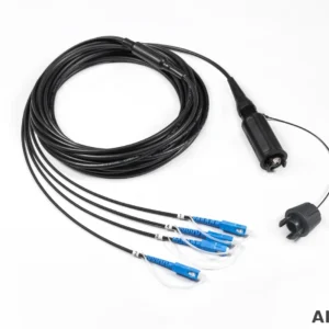
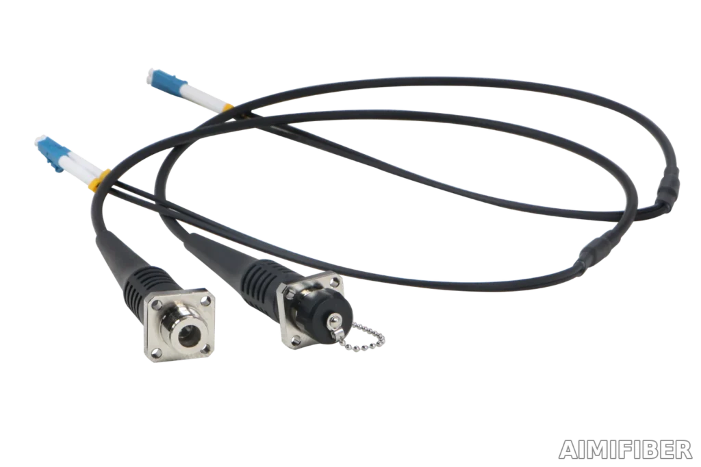
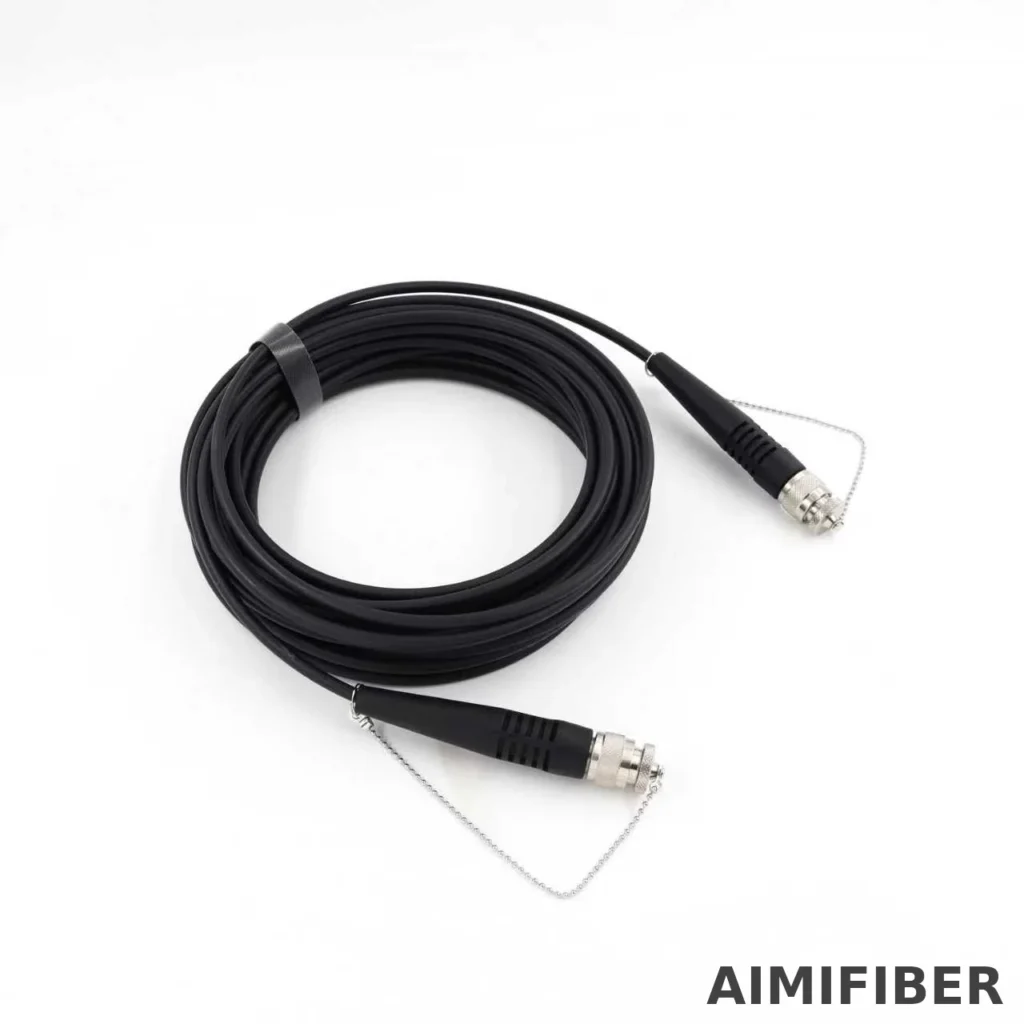
ODC ruggedized fiber assemblies combine a sealed outdoor connector (plug/socket) with outdoor-grade cable to deliver reliable links in harsh environments (FTTA base stations, small cells, substations, roadside CCTV, rail, offshore/onshore industrial sites).
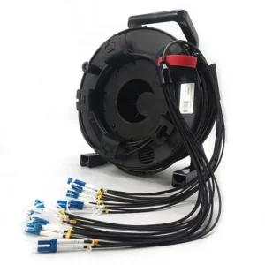
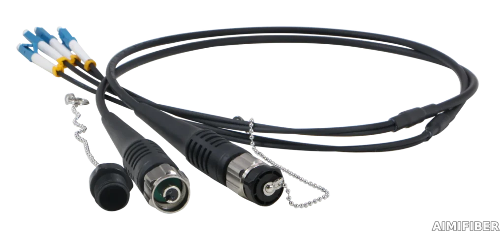
Choose ODC 2/4 core for simple point-to-point RRH/RRU drops; choose ODC–MPO (4–24 fibers) when multi-fiber fan-out, density, and fast deployment are required (e.g., ODC–MPO to 4×LC breakout).
At-a-Glance Comparison
| Item | ODC 2/4 Core | ODC–MPO (4–24F) |
|---|---|---|
| Fiber count | 2F / 4F (SM/MM) | 4F/6F/8F/12F/24F (SM/MM) |
| Ferrule type | Ceramic (discrete) | MT ferrule (MPO/MTP-style) |
| Typical use | FTTA to 1–2 device ports | Multi-port fan-out, high density |
| Blind-mate & locking | Yes | Yes |
| Ingress protection | IP67–IP68 (mated) | IP67–IP68 (mated) |
| Common transition | ODC–ODC | ODC–MPO to 4×LC/SC |
Optical Performance (Assembly, per mated pair)
| Parameter | ODC 2/4 Core | ODC–MPO (SM) | ODC–MPO (MM) | Notes |
|---|---|---|---|---|
| Insertion Loss (typ.) | ≤0.8 dB | < (1.6 + 0.0003 × L) dB @1310/1550 nm | < (1.2 + 0.003 × L) dB @850/1300 nm | L = cable length (m) |
| Return Loss | ≥50 dB (SM), ≥35 dB (MM) | ≥50 dB (SM) | ≥30 dB (MM) | At reference connector |
| Fiber types | SM G.652D/G.657A1/A2 | SM G.652D/G.657A1/A2 | MM OM1/OM2/OM3/OM4 | G.657A2 recommended for tight bends |
Mechanical & Environmental
| Parameter | Value | Notes |
|---|---|---|
| Ingress protection | IP67–IP68 (mated) | Use sealing caps on unmated ends |
| Operating temperature | −40 °C ~ +80/+85 °C | Model dependent |
| Storage temperature | −55 °C ~ +85 °C | |
| Mating durability | ≥100 cycles | Typical ODC/ODC–MPO hardware |
| Tensile (plug/assembly) | Plug ≥100 N; Socket/assembly ≥400–500 N | Pull via strength member |
| Vibration | 10–500 Hz, up to 10 g | Per IEC/GR profiles (project-specific) |
| Shock | 50 g, 11 ms | 3-axis |
| UV/Weather | UV-resistant jacket | For outdoor exposure |
| Salt fog / Dust | Supported with proper caps | Maintenance schedule recommended |
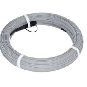
Cable & Jacket Options
| Cable Type | OD (typ.) | Sheath | Application |
|---|---|---|---|
| Outdoor trunk (UV) | 5.0–6.0 mm | PE/TPU (UV) | Outdoor runs, towers, masts |
| Tactical TPU | 5.5 mm | TPU | Rugged field deployment |
| Indoor transition | 2.0 mm | LSZH/PVC | ODC–MPO to device patching |
| Buffered pigtail | 0.9 mm | LSZH | Panel/box fan-out |
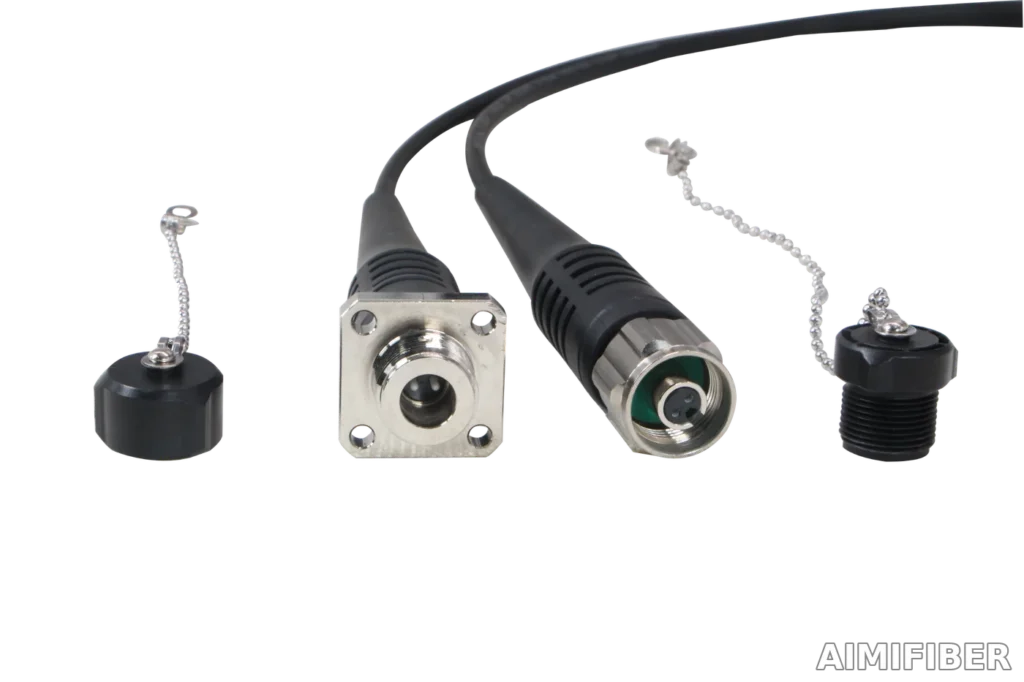
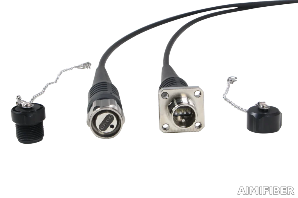
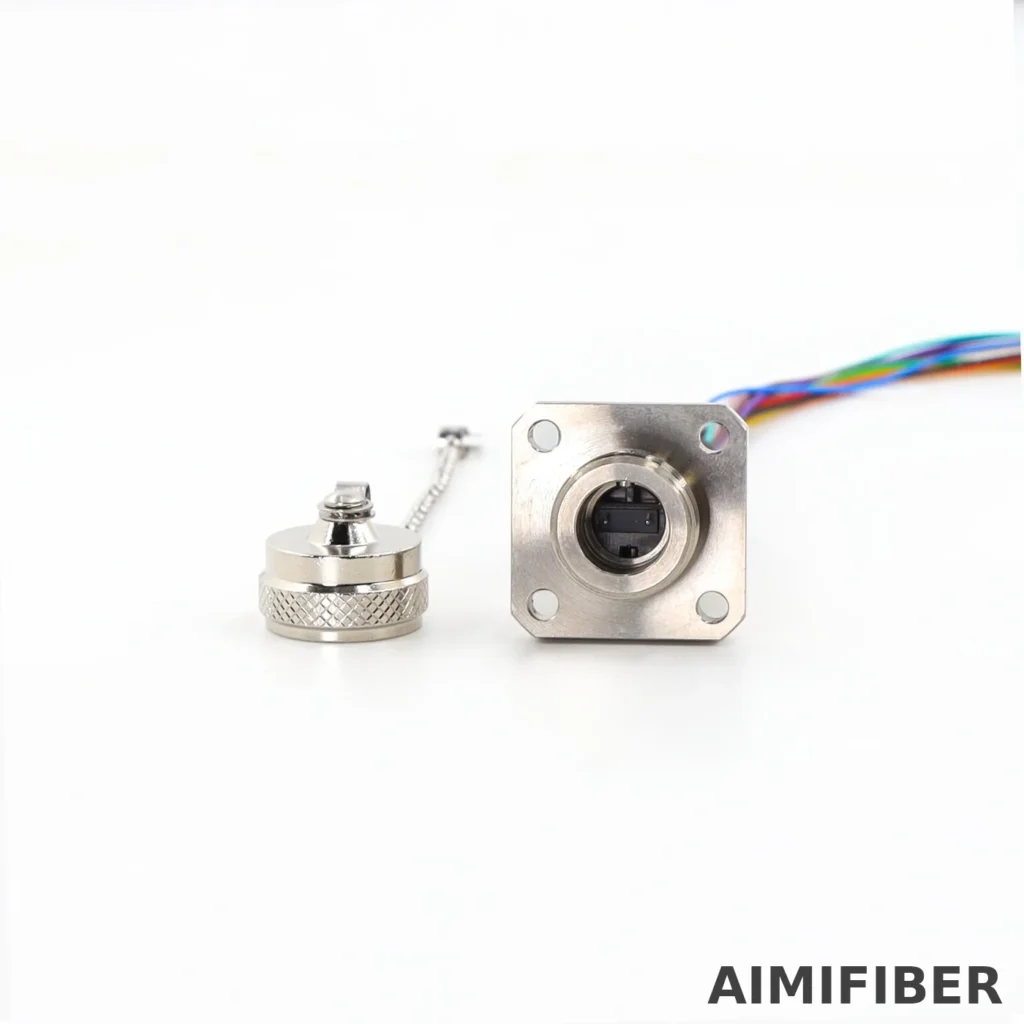
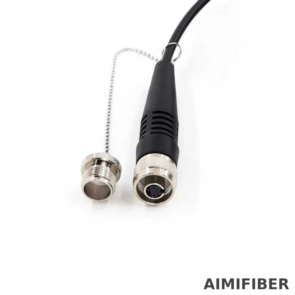
Interface & Mating
| Item | Spec | Notes |
|---|---|---|
| Guide/keying | Yes | Blind-mate orientation |
| Locking | Rotational / threaded | Finger-tight + 1/8–1/4 wrench turn |
| Install torque | ~1–2 N·m | Follow the model sheet |
| Dust/water caps | Included | Keep on all unmated ends |
| Polarity (MPO) | Type A/B/C | Confirm with port map |
| Gender (MPO) | Pinned/Unpinned | Match device harness |
Compliance & Testing
| Standard/Test | Scope |
|---|---|
| IEC 61300 series | IL/RL, durability, environmental |
| IP67/IP68 | Ingress protection when mated |
| RoHS/REACH | Materials compliance |
| Optional CPR | For indoor sections (EU), upon request |
| 100% test | IL/RL report per reel/leg |
Installation Guidelines (Quick Reference)
| Topic | Recommendation |
|---|---|
| Bend radius | Installation ≥20×OD; Operation ≥10×OD (unless stated otherwise) |
| Pulling | Use swivel and pull via strength member; avoid pulling on connector |
| Clamping | Use cushioned clamps; avoid sharp edges |
| Labeling | Use ID labels + meter marks for asset tracking |
| Caps | Keep caps on until final mating; re-cap when unmated |
| MPO cleaning | Dry cassette cleaner / lint-free swab; avoid alcohol pooling |
ODC 2/4 Core — Detailed Specification
| Parameter | Spec | Notes |
|---|---|---|
| Fiber count | 2F / 4F (SM/MM) | |
| IL/RL (per mated pair) | ≤0.8 dB (typ.); RL ≥50 dB (SM) | At reference connector |
| Connector tensile | ≥500 N (mated retention) | Model dependent |
| Durability | ≥100 mating cycles | |
| Temperature | −40 °C ~ +85 °C | |
| IP rating | IP67–IP68 (mated) | With sealing cap on unmated |
| Cable | UV-resistant PE/TPU | Outdoor grade |
ODC–MPO (4–24F) — Detailed Specification
| Parameter | Spec | Notes |
|---|---|---|
| Ferrule | MT (MPO/MTP-style) | Metal-housed ODC |
| Fiber counts | 4F/6F/8F/12F/24F | SM/MM |
| IL formula (SM) | < (1.6 + 0.0003 × L) dB @1310/1550 nm | L in meters |
| IL formula (MM) | < (1.2 + 0.003 × L) dB @850/1300 nm | L in meters |
| Return loss | ≥50 dB (SM), ≥30 dB (MM) | |
| Durability | ≥100 mating cycles | |
| Temperature | −40 °C ~ +80/+85 °C | |
| IP rating | IP67–IP68 (mated) | |
| Polarity | Type A/B/C | Confirm at order |
| Gender | Pinned/Unpinned | Match device harness |
ODC–MPO to 4×LC (Breakout) — Specification
| Parameter | Spec | Notes |
|---|---|---|
| Transition | ODC–MPO to 4×LC (or 4×SC) | Device-side ports |
| LC end IL/RL | ≤0.3 dB (IL), RL ≥50 dB (SM) | Typical values |
| Fan-out length | Custom | 0.5–3 m common |
| Sheath | UV outdoor → indoor LSZH | Outdoor-to-indoor |
| Temperature | −40 °C ~ +80 °C | |
| IP at ODC side | IP67–IP68 (mated) | Use caps when unmated |
Ordering Matrix (Fill-in)
| Field | Options | Example |
|---|---|---|
| System | ODC 2F / ODC 4F / ODC–MPO 4/6/8/12/24F | ODC–MPO 12F |
| Fiber | SM G.652D / G.657A1/A2 / MM OM1/OM2/OM3/OM4 | SM G.657A2 |
| Ends | ODC–ODC / ODC–MPO / ODC–MPO to 4×LC (or 4×SC) | ODC–MPO to 4×LC |
| Length | 10/20/30/50/100 m or custom | 50 m |
| Cable | UV PE/TPU 5–6 mm / 2.0 mm / 0.9 mm | TPU 5.5 mm |
| IP rating | IP67 / IP68 | IP68 |
| Labels | Meter marks / Port IDs / Custom | Port-ID + meters |
Example code: ODC-MPO | 12F | SM G657A2 | ODC–MPO to 4×LC | 50m | IP68 | TPU5.5 | Port-ID | ODC–MPO to 4×LC | 50m | IP68 | UV
FAQ (English-only)
1) What is an ODC ruggedized fiber assembly and when should I use it?
An ODC assembly combines a sealed outdoor connector (plug/socket) with outdoor-rated cable for harsh sites (FTTA base stations, roadside CCTV, rail, substations). Use it wherever dust, rain, UV, and vibration make standard indoor patch cords unreliable.
2) ODC 2/4-core vs ODC–MPO: how do I choose?
Choose ODC 2/4 core for simple point-to-point drops to one or two ports. Choose ODC–MPO (4–24F) when you need multi-fiber fan-outs or faster install with fewer cables.
3) What IP rating do ODC connectors achieve?
Most builds are IP67–IP68 when properly mated and capped. IP ratings assume the correct torque/locking is applied and that caps are used on unmated ends.
4) Can the connector be submerged?
Short-term immersion is supported on IP68 builds. Always check the datasheet limits (depth/time) and ensure the connector is fully mated before exposure to water.
5) How many mating cycles are supported?
Typical ODC/ODC–MPO hardware supports ≥100 cycles (some 2/4-core variants higher). For long life, keep dust caps on and avoid cross-threading.
6) Is there a recommended tightening torque?
Yes—ODC sockets usually specify ~1–2 N·m install torque. Finger-tight plus a small wrench turn is common; follow the specific model’s instruction sheet.
7) Are ODC connectors keyed? Can I blind-mate them?
Yes. They have guide/key features for orientation and quick blind-mating on towers and in enclosures.
8) What fiber types are supported?
Single-mode G.652D / G.657A1/A2 and multimode OM1/OM2/OM3/OM4 are standard. G.657A2 is recommended for tight routing at RRUs.
9) What insertion loss/return loss should I plan for?
Typical assembly budgets:
- ODC–MPO (SM): IL < (1.6 + 0.0003 × L) dB @1310/1550 nm
- ODC–MPO (MM): IL < (1.2 + 0.003 × L) dB @850/1300 nm
- 2/4-core ODC: often ≤0.8 dB per mated pair (model-dependent)
(L = cable length in meters.) Always add device-side connector loss if using breakouts.
10) MPO polarity and gender—what do I need to specify?
Specify polarity (Type A/B/C) and gender (pinned/unpinned) to match your radio/BBU harness. If uncertain, send your port map; we’ll provide a matched pinout.
11) Can I do ODC–MPO to 4×LC (or 4×SC) breakouts?
Yes. This is common for FTTA. Confirm fan-out length, fiber mapping, and connector type (LC/SC, UPC/APC for SM).
12) What cable diameters and bend radii are typical?
Outdoor trunks are commonly 5.0–6.0 mm OD; minimum bend radius is typically 10×OD (operation) / 20×OD (installation) unless otherwise specified.
13) What is the allowable pulling tension?
Typical install tensions are ≥100 N for plugs and ≥400–500 N for sockets/assemblies (model-specific). Use a swivel and pull by the strength member, not the connector.
14) How do I protect against UV, sand, and salt fog?
Use UV-resistant jackets and keep sealing caps on unmated ends. For coastal/saline sites, request corrosion-resistant hardware and consider periodic inspection.
15) What cleaning is required in the field?
Keep caps on, blow off debris, and for MPO ends use dry cassette cleaners or lint-free swabs. Avoid alcohol pooling inside the interface; let parts dry before mating.
16) Can I re-terminate ODC connectors in the field?
Generally no—they are factory-terminated and tested. For repairs, replace the assembly or use a spare pre-terminated unit.
17) Are ODC assemblies compatible across vendors?
ODC is a ruggedized outdoor family; dimensions, keys, and tolerances can vary by vendor. Do not assume intermateability—share your target hardware so we can validate.
18) What documentation ships with the product?
Assemblies ship with 100% IL/RL test reports (per reel/leg). Additional environmental or vibration test summaries are available on request.
19) What lengths and labeling can I order?
Standard lengths include 10/20/30/50/100 m; custom lengths and ID labels/meter marks are available for asset tracking.
20) What are the lead time and MOQ?
Typical lead time is 7–12 days for samples, 2–4 weeks for batch, with flexible MOQ. Exact timing depends on fiber count, cable type, and connectors.