How Do Pre-Terminated Fiber Solutions Keep Data Center Projects On Schedule?

Deadlines are tight and racks keep arriving. Field termination slows everything and adds risk. I have seen good teams lose weeks to rework and hunt for dust on ferrules. Pre-terminated fiber removes the bottleneck with factory-built, plug-and-play assemblies that land on site ready to route and connect.
Pre-terminated fiber solutions cut installation time by 40–80% because there is no on-site connector work. Each link ships with verified insertion loss and return loss, so performance is predictable from day one. You deploy faster, reduce specialist labor, and avoid most commissioning surprises that push go-live dates.
Ryan, a project manager on a U.S. hyperscale build, was worried about late nights and failed links during turn-up. We replaced field termination with pre-terminated trunks, cassettes, and labeled harnesses. His team pulled, plugged, verified, and moved to the next row. The build stayed on schedule and the budget stayed intact.
Why Are Pre-Terminated Assemblies Faster and More Reliable Than Field Termination?

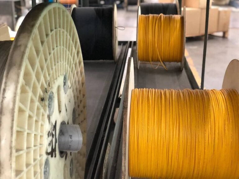
You cannot afford variable quality when a row must ship this week. Field work depends on skill, tools, and a clean area. Pre-terminated assemblies move the critical steps into a controlled cleanroom with automated polishing and inspection. You receive links that already meet spec.
Each assembly eliminates on-site stripping, cleaving, polishing, and connector inspection. Cleanroom end-face inspection follows IEC criteria, and multifiber ferrule geometry is measured to standardized methods1. Factory termination and 100% test records replace guesswork with proof. Your team routes the cable, protects the bend radius, and plugs in. That is the whole job2.
The Factory Advantage
Process Control You Can Trust
- Machine-polished end-faces meet geometry targets for apex offset and radius of curvature3.
- Automated inspection finds scratches, pits, and debris to IEC pass/fail rules.
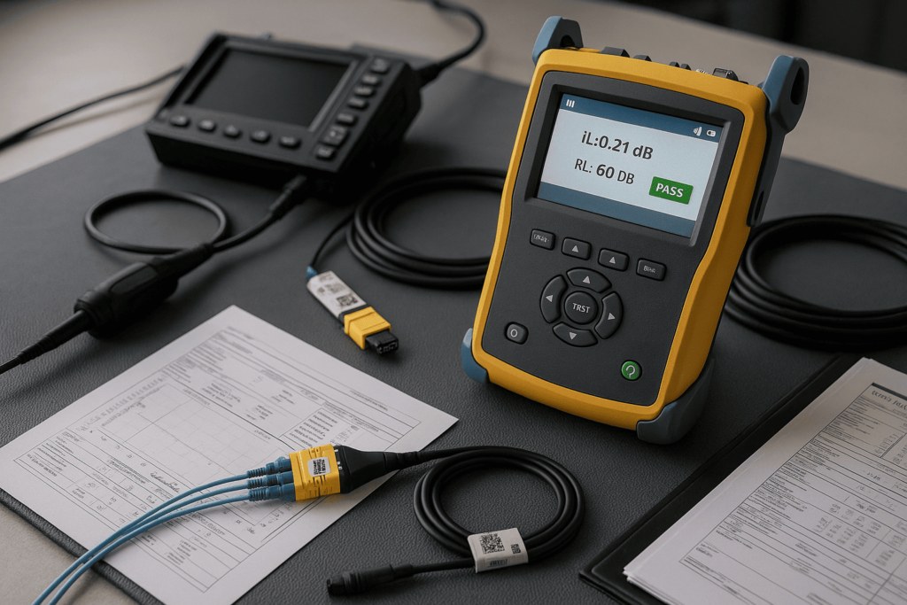
- 100% IL/RL testing documents performance for every leg; IL/RL definitions and testing basics are here45.
Task Time Comparison (per 100 links)
| Step | Field Termination | Pre-Terminated |
|---|---|---|
| Strip / Cleave / Polish | 40–50 hours | 0 hours |
| On-site Testing & Fixes | 10–15 hours | 2 hours |
| Rework & Troubleshooting | 5–10 hours | 0–1 hour |
| Total (excluding pulls) | 55–75 h | 2–3 h |
Acceptance Targets I Use
| Metric | Typical Target (Single-Mode) |
|---|---|
| IL (LC/SC, per mated pair) | ≤ 0.30 dB |
| IL (MTP 12F, per pair) | ≤ 0.35 dB |
| RL (UPC/APC) | ≥ 50 / ≥ 60 dB |
| Ferrule Cleanliness | No core/adjacent defects |
Tip: Ask for the CSV of test results for direct import to your CMDB. It saves hours at hand-over. Component and field-testing requirements are outlined in ANSI/TIA-568.3-E.
Can Pre-Terminated Fiber Fit My Data Center Architecture?
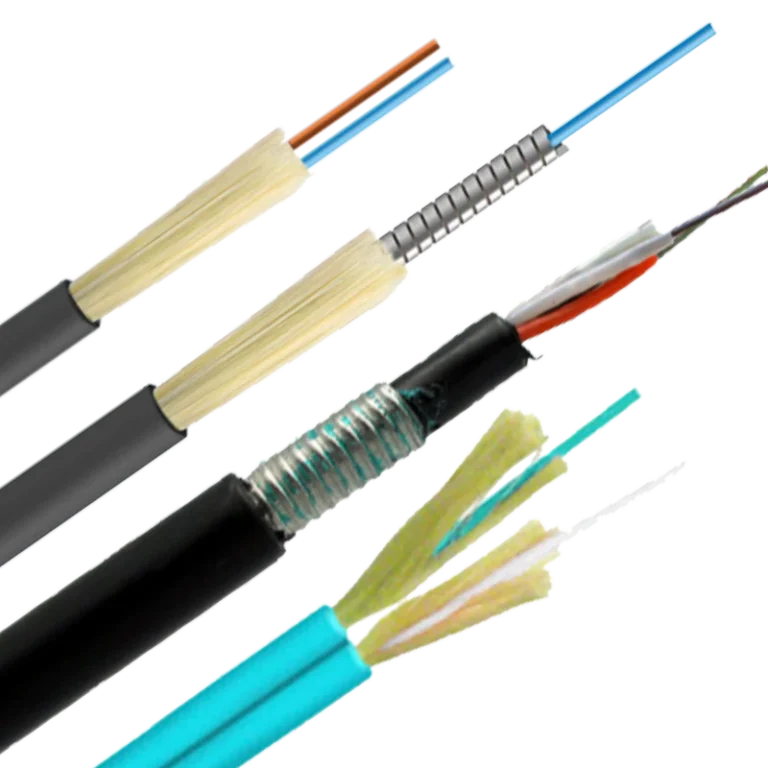
Yes. Pre-terminated cabling is built to your drawings, not the other way around. It supports spine-leaf, modular pods, and brownfield retrofits. You pick trunk lengths, polarity, fiber type (OS2 / OM4 / OM5 per ISO/IEC 11801), connector maps, and labeling so every route lands where your devices live today67.
Custom assemblies map to greenfield and live upgrades. In a spine-leaf, high-count MTP trunks land in cassettes that break out to LC. In an edge or collapsed-core room, MTP-to-LC harnesses reduce patch chaos. For brownfield work, measured lengths and pulling eyes reduce dust, noise, and time in hot aisles89.
Topologies and Recommended Builds
| Topology | How It Helps You | Recommended AIMIFIBER Build |
|---|---|---|
| Spine-Leaf | Rapid row turn-ups; high density between tiers | MPO/MTP Trunk Cable + cassettes |
| Modular Pods | Repeatable kits; easy scale by pod count | Pre-kitted trunks + cassettes |
| Collapsed Core | Simple distribution; fewer moving parts | MTP-to-LC Harness/Breakout |
| Brownfield | Measured lengths; minimal on-site work | Custom-length patch cords |
Polarity and Keying Made Simple
| Polarity Scheme | Use Case | Notes |
|---|---|---|
| Type A | Legacy mixed environments | Straight through |
| Type B | Parallel optics, many 40/100/400G | Flipped map for transceiver pinouts |
| Type C | Duplex breakout to LC | Pair-wise flip for send/receive |
I include a one-page polarity map on every order so installers see the exact fiber positions at a glance. Polarity schemes are covered in TIA cabling standards10.
What Specs, Labels, and Documents Should I Request Before Placing a PO?
Your PO is the best place to lock performance and documentation. If you specify it up front, acceptance is smooth and audits are simple.
Procurement & Documentation Checklist
Cable & Connector Specs
- Fiber type OS2 / OM4 / OM5 (bend-insensitive options per ITU-T G.657 for tight spaces and trays)11.
- Jacket material LSZH (indoor) or PE (inter-building/outdoor).
- Connector type LC/SC or MTP/MPO (8/12/24F); ferrule grade stated.
- Polarity Type A/B/C and keying for MTP (match optics).
Labeling & Traceability
| Field on Label | Why It Matters |
|---|---|
| Unique Serial/QR | Inventory and warranty look-ups |
| From/To Port IDs | Error-free patching |
| Cable Length & Fiber Type | Capacity and spares planning |
| Batch / Reel ID | Full trace back to test data |
Test & Quality Docs
- Factory IL/RL results per leg (PDF + CSV)45
- Visual end-face images (sample per batch) per IEC inspection
- Compliance: CPR (EN 50575) for EU projects and NFPA 70/NEC context in the U.S.1213
- Delivery map matching your rack/row naming
- If you design to availability targets, align with Uptime Institute Tier expectations for upgrade windows and risk14.
What Installation Plan Minimizes Risk and Downtime?
A simple, repeatable playbook turns chaos into speed. I keep this card in every tool bag.
My 9-Step Row Turn-Up
- Verify drawings and polarity maps
- Stage reels by row, confirm labels match ports
- Pull with mesh pulling eye, cap connectors until final plug-in
- Respect bend radius ≥ 20× OD; never exceed 50 N per pull on jumpers
- Land trunks, install cassettes, hand to patch team
- Clean and inspect all end-faces just before mating (IEC criteria)
- OLTS test each link; spot OTDR any outliers (FOA test refs)
- Export CSV results to CMDB; attach photos of panels
- Handover sign-off with IL/RL summary and as-built
Roles & RACI Snapshot
| Task | PM | Cabling Crew | Fiber Tech | QA |
|---|---|---|---|---|
| Staging & labeling | R | A | C | I |
| Pull & routing | I | A/R | C | I |
| Cleaning & mating | I | C | A/R | I |
| Testing & sign-off | C | I | A/R | A |
What ROI Can I Expect and How Do I Model It?
Executives want numbers, not adjectives. The model below uses realistic ranges I see on jobs. Adjust the variables to your labor rates and link counts. For overall data center design context, see BICSI’s reference standard15.
Simple ROI Model (Illustrative)
| Item | Field Termination | Pre-Terminated |
|---|---|---|
| Labor hours per 100 links | 70 h | 20 h |
| Blended labor rate | $85/h | $85/h |
| Labor cost | $5,950 | $1,700 |
| Scrap/rework (connectors, time) | $1,200 | $200 |
| Test gear rental & consumables | $800 | $200 |
| Subtotal (per 100 links) | $7,950 | $2,100 |
| Revenue delay (1 week @ \$10k/d) | $70,000 | $0–$10,000 |
| Total impact | $77,950 | $12,100 |
Even when unit cable price is higher, the project-level savings and earlier service activation dominate the business case.
Conclusion
Pre-terminated fiber turns a risky and slow phase into a fast, predictable step. Cleanroom-built links, labeled to your plan and verified with IL/RL data, let your team pull, plug, and move on. The result is shorter schedules, fewer on-site specialists, and smoother hand-overs. If your next row must go live on a fixed date, build it with pre-terminated trunks, cassettes, and harnesses from AIMIFIBER.
Summary
I explained why pre-terminated assemblies beat field termination on speed and reliability, how they map to spine-leaf and pod designs, which specs and documents to lock in at PO time, and how to install with a repeatable nine-step plan. I closed with a simple ROI model that shows why pre-terminated wins at the project level—even before you count fewer headaches.
IEC 61300-3-35 — End-face inspection criteria for fiber optic connectors (IEC Webstore). ↩
Overview of field-terminated vs pre-terminated fiber methods and trade-offs, Windy City Wire explainer. ↩
IEC 61300-3-30 — Measurement of end-face geometry for rectangular multifiber ferrules (IEC Webstore). ↩
FOA — Insertion loss testing and expected loss guidelines (FOA reference). ↩ ↩
FOA — Reflectance/optical return loss basics and testing (FOA reference). ↩ ↩
ISO/IEC 11801-1 — Generic cabling requirements (ISO). ↩
ISO/IEC 11801-5 — Data centers cabling specification (ISO Online Browsing Platform). ↩
Rapid deployment advantages and programmatic time savings for data center builds using pre-terminated systems, Hexatronic Data Center knowledge article. ↩
How pre-terminated cabling maps to data-center designs and deployment playbooks, AIMIFIBER deployment guide and product pages (trunks, cassettes, breakouts). ↩
ANSI/TIA-568.3 (latest revision “.3-E”) — Optical fiber cabling and component standard (TIA announcements/overview). ↩
ITU-T G.657 — Bend-insensitive single-mode fiber recommendation (ITU). ↩
EU Construction Products Regulation (CPR) and EN 50575 context for cables used in construction works (European Commission). ↩
NFPA 70 (NEC) — U.S. electrical code context for communications and fiber cabling (NFPA). ↩
Uptime Institute Tier Standard — Availability design targets and certification program (Uptime Institute). ↩
ANSI/BICSI 002 — Data center design standard and methodology (BICSI). ↩