Are you planning an FTTH network for a multi-dwelling unit (MDU)?
The wrong splitter choice can cause signal issues and expensive future upgrades. But with a clear strategy, you can build a reliable network that lasts.
Proper FTTH splitter planning involves choosing the right split ratio, like 1x8 or 1x16, based on subscriber density. Then, you must calculate the total signal loss (loss budget) and design a flexible floor distribution to accommodate future growth and simplify maintenance.
I remember working with my client, David, on a large project for Telefonica in South America. The building had hundreds of units. Choosing the right splitter architecture was the most critical decision we made. It determined the project's success for years to come.
Which FTTH Splitter Ratio Is Right for Your Project?
Choosing the splitter ratio seems simple, but it impacts your network's reach, CAPEX/OPEX, and upgrade path. In MDUs, I start with subscriber density per floor/zone, then check the optical loss budget against your PON class (GPON/XGS-PON) and add future growth headroom.
Select a splitter ratio by subscriber density and total optical path loss. Lower ratios (1×4, 1×8) give lower insertion loss and longer reach; higher ratios (1×16, 1×32) maximize port count in dense buildings but eat more budget. Always keep margin for aging, patch moves, and dirt.
Typical splitter performance (PLC, single-mode, APC)
Values are typical; confirm with vendor datasheet. Splitter Insertion Loss (dB) Uniformity (dB) Return Loss (dB) Note 1×4 ~7.3 ≤0.8 ≥55 Good for long risers / low count 1×8 ~10.5 ≤1.0 ≥55 Common “per-floor” choice 1×16 ~13.5 ≤1.2 ≥55 Popular in medium/large MDUs 1×32 ~17.0 ≤1.5 ≥55 Centralized high-density hubs 1×64 ~20.5 ≤2.0 ≥55 Use only if budget allows
Loss budget (quick worksheet)
Total loss = Fiber attenuation + Splitter loss + Connectors + Splices + Margin
(Typical: fiber 0.35 dB/km @1310 nm; connector 0.2 dB; splice 0.1 dB; design margin ≥3 dB)
Example (MDU, 1×16 centralized):
Feeder 5 km (0.35×5=1.75 dB) + riser 0.5 km (0.18 dB) + 1×16 splitter (13.5 dB) + 6 splices (0.6 dB) + 4 connectors (0.8 dB) + margin 3 dB
→ Total ≈ 19.9 dB (fits many GPON/XGS-PON budgets; verify vendor class)
Ratio quick guide (density-driven)
| Split Ratio | Max Subscribers | Recommended Scenario | Typical Max Distance* |
|---|---|---|---|
| 1×4 | 4 | Small/low-take-up floors, long feeder | 20–40 km |
| 1×8 | 8 | Per-floor split in 8–12 unit zones | 20–40 km |
| 1×16 | 16 | Medium floors; single riser serving two floors | ~20 km |
| 1×32 | 32 | Dense MDUs; centralized hub cabinet | ≤20 km |
*Distance is a function of total loss. Always compute your budget.
Pro tip: If uptake is uncertain, start with 1×8 distributed and leave space/connectors to upgrade to 1×16 later. It’s cheaper than replacing a fully centralized 1×32 setup that runs out of budget.
Where Should You Place Your Splitters: Centralized or Distributed?
Placement shapes cable routes, serviceability, and growth options. Decide with access, density, and construction constraints in mind. For many MDUs I use a centralized or cascaded riser strategy, then push small splitters closer to subscribers when uptake is phased.
Centralized puts everything in one hub for easy maintenance; distributed/cascaded brings splitters to the floor or zone for flexibility and shorter horizontal runs.
1) Centralized Architecture
All splitters in one FDH (basement/telecom room). Home runs to each unit or floor box.
- Best for: Predictable, high-density MDUs with strong initial take-up.
- Pros: One maintenance point; easy labeling and inventory.
- Cons: Higher horizontal cabling; upgrades can be disruptive if budget tight.
Tip: Use 1×32 with spare ports and label by floor/stack. Keep pre-terminated trunks to speed changes.
2) Distributed Architecture
Riser fiber up the shaft; a 1×8 or 1×16 per floor/zone.
- Best for: Phased activation or uncertain take-up.
- Pros: Very flexible; minimizes cables per floor; easy adds.
- Cons: Techs must access multiple cabinets; track inventory carefully.
Tip: Standardize floor boxes (same SKU), and reserve a cleaning kit + power budget card inside each.
3) Cascaded Architecture (1st stage → 2nd stage)
Primary 1×4 in the basement feeding 1×8 per floor (1×32 total).
- Best for: Large MDUs or campus buildings with long vertical runs.
- Pros: Efficient use of feeder; excellent coverage.
- Cons: Budget math is stricter; two split stages add loss.
Rule of thumb: Keep two-stage split only when cabling constraints justify it—validate with a budget calculator and leave ≥3 dB margin.
Design checklist (use before RFQ)
| Step | What to decide | Typical choice | Notes |
|---|---|---|---|
| Topology | Centralized / Distributed / Cascaded | Per building | Driven by access & density |
| Split ratio | 1×8 / 1×16 / 1×32 | Mix by floor | Leave growth room |
| Connector | SC/APC (green) | PON/MDU standard | RL control through splitters |
| Patch model | Pre-terminated or field | Pre-term preferred | Faster & cleaner installs |
| Cabinet/box | IP/fire rating, lock, space | FDH + floor boxes | Plan for extra slack |
| Labeling | Port/floor/unit scheme | Color + QR | Avoid miscabling |
| Budget | Worst-path computation | ≥3 dB margin | Add aging/contamination |
| Testing | LSPM + OTDR | One-card SOP | Keep before/after data |
Procurement & QA (what I ask suppliers for)
| Item | Spec to confirm | Document |
|---|---|---|
| PLC splitter | Insertion loss, uniformity, RL (APC), PDL | Factory test sheet (SN-matched) |
| Pigtails/jumpers | IL ≤0.30 dB (typ.), RL ≥60 dB (APC) | IL/RL report + endface photo |
| Floor boxes/FDH | Capacity, bend radius, lock, labeling | Datasheet + layout drawing |
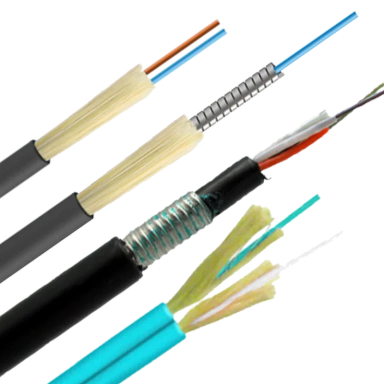
| Trunks | Fiber type (G.657.A2), length, connectors | Polarity map + test report |
| Labels | Color code, port map, engraving/QR | Sample photo before ship |
Internal links (for your build):
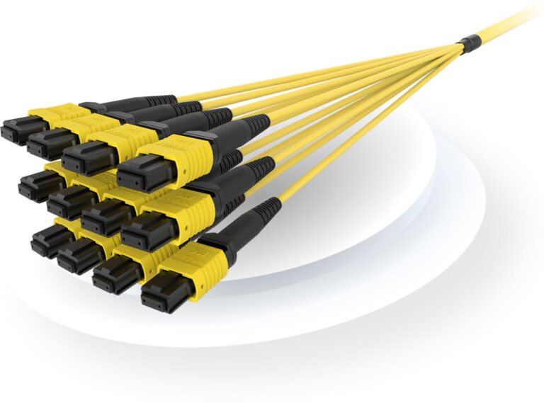
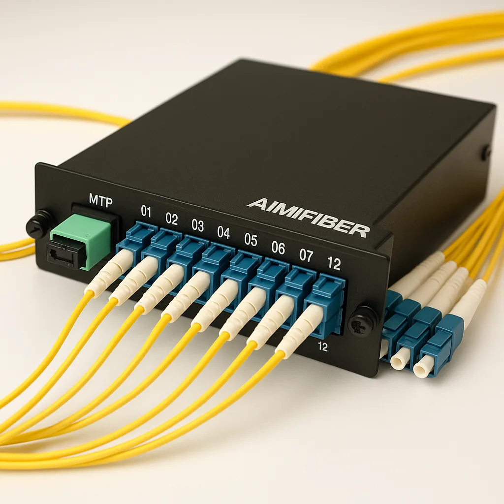
- Pre-terminated options: AIMIFIBER MTP/MPO trunks & LC cassettes
- Patch cords: Fiber Patch Cables (SC/APC/LC/UPC)
Final thoughts
Get the ratio right for density today, leave margin for tomorrow, and choose placement that your technicians can service without drama. Do the math (budget), label everything, and verify with LSPM + OTDR at handover. Need a one-page MDU splitter budget worksheet? Email sophie@aimifiber.com—I’ll share the template I use on EU/LatAm projects.
FAQ
Q1: Should I standardize on 1×16 or mix 1×8 and 1×16?
Mixing is practical: use 1×8 on low-uptake floors and 1×16 where density is proven. Keep space to add a second splitter later.
Q2: Can I use 1×32 everywhere to save rack space?
Only if the loss budget allows it. 1×32 adds ~17 dB on its own—fine for short paths, risky for long feeders or cascades.
Q3: Is cascaded splitting (1×4 → 1×8) safe for XGS-PON?
Yes, if the total loss (fiber + two split stages + connectors/splices + margin) stays within your OLT/ONT budget class. Run the numbers first.
Q4: Which connector should I use on splitters in MDUs?
Use SC/APC for PON paths to control back-reflection through splitters. Keep UPC for CO/density patching—do not cross-mate APC/UPC.
Q5: What acceptance data do I need for handover?
Per-port IL (LSPM) at 1310/1490/1550 (as applicable), OTDR traces with launch/receive fibers, endface photos, and a port/floor/unit label map.